Lester's Custom Truck Shop
United States
Webmaste
8719-192-L2-PLCC Cobra 148/148F KIT INSTRUCTIONS

There are several different versions of the Cobra 148. The instructions presented here are for the most common types. Denoted by a side mounted microphone connector. These instructions also apply to the President or Uniden Grant.
NOTE: RADIO MUST BE IN ORIGINAL CHANNEL CONFIGURATION. ALL CHANNEL MODS MUST BE REMOVED AND COMPONENTS RETURNED TO ORIGINAL CONDITION.
Presteps;
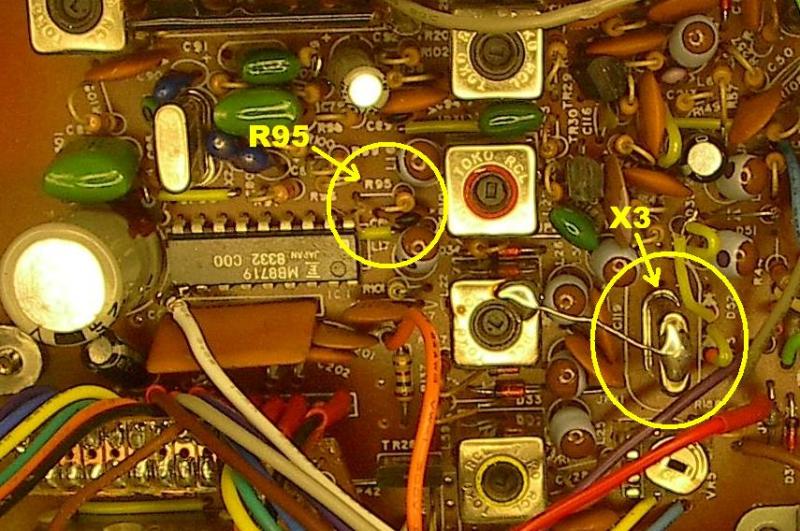
It is recommended you replace X3 (11.3258) with the enclosed xtal. If you replace the crystal with the one in the kit, parallel D35 with an SV251 varactor diode. (Cathode to cathode, anode to anode). This will give more slide and lower the frequency slightly.
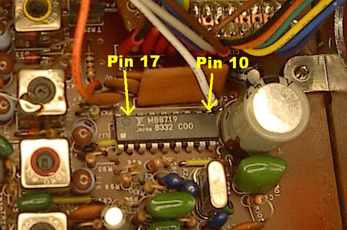
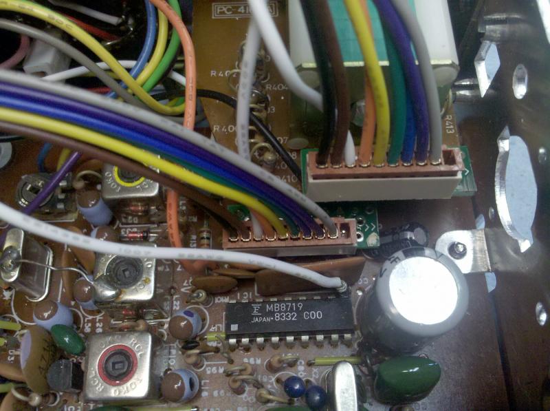
Connect the WHITE wire from connector J3a to pin 10 of the PLL on the top of the IC.
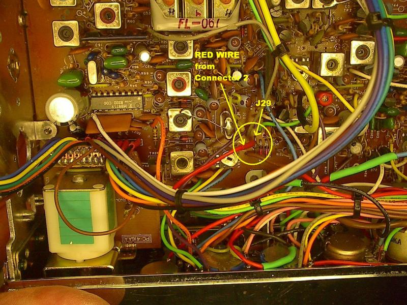
Connect the RED wire from connector J3a to J29 as shown. This is the best place to pick up a clean 8 volts.
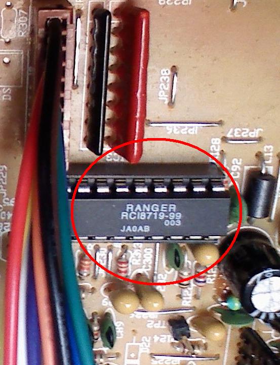
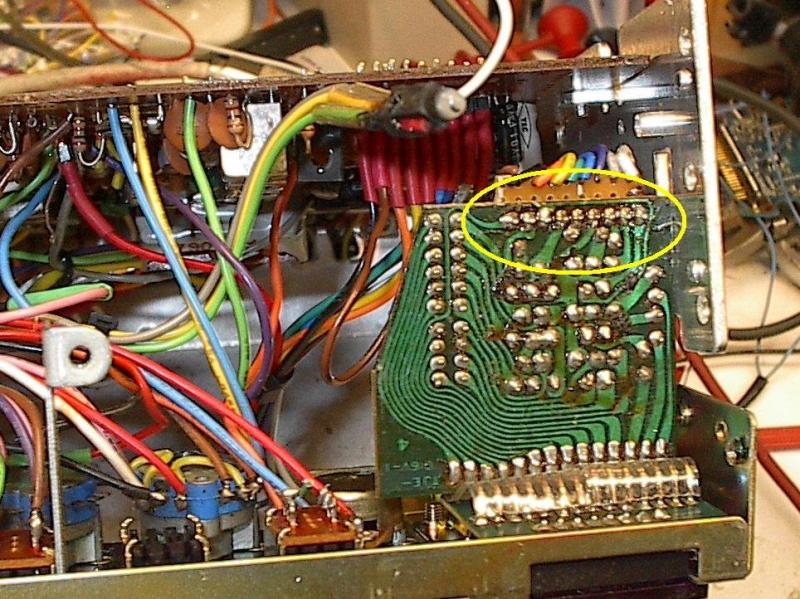
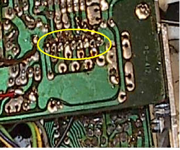
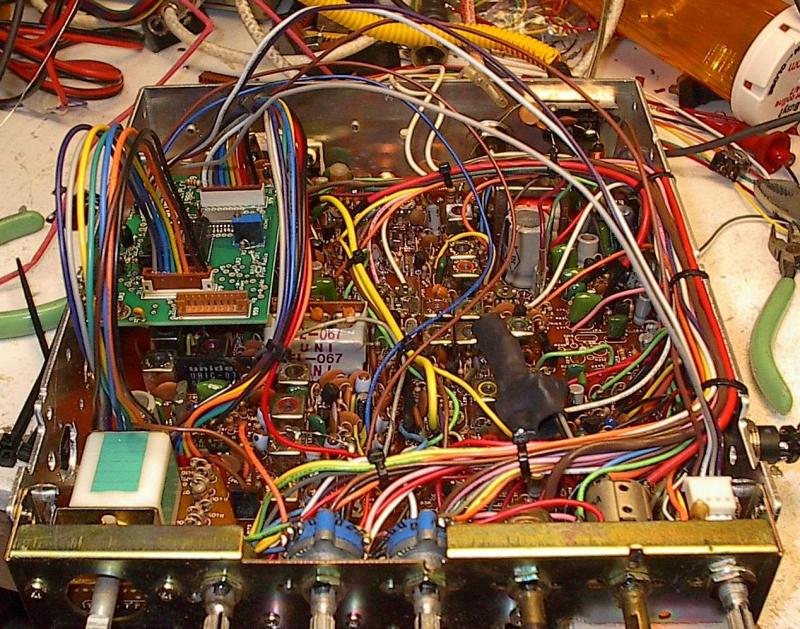
Ranger made Cobra’s and Texas Ranger TR296/296F, Refer to figure 1. If your PLL IC is labeled like the one in this pic “RCI 8719-97”. Replace the PLL IC with either an RCI8719-99, an MMB8719 or an MB8719 and then replace the crystal with the one in the kit.
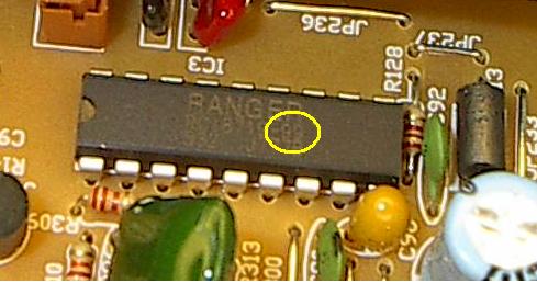
If your radio has the PLL IC labeled “RCI 8719-99” replace the crystal with the one in the kit.
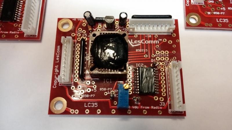
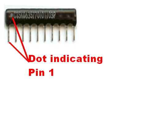
In both cases, install RA1 common pin to the +5 hole (pull up). This is already done on boards assembled after 8/1/09.
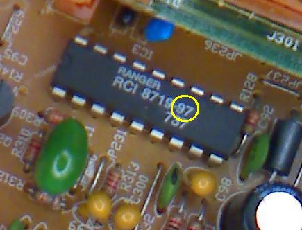
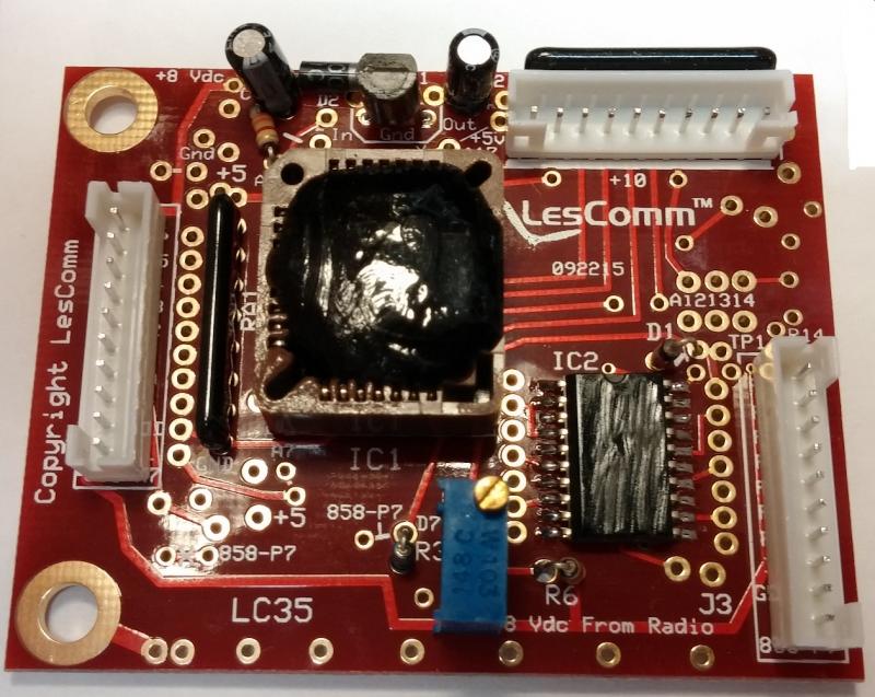
Figure 1.
Take note of the connector labels. One pair is for the 959 style chassis (939, 949, 959, 969, 696, FD-1, 699, 2547 etc.).
The other pair is for the 979 style chassis, (919, 929, 979).
For the Cobra type radio’s, use the connectors labeled “979”. On the L2 boards, the connectors are now labeled "Cobra". The 959 connectors should not be installed on Cobra boards assembled after 8-1-09.
CAUTION! Connecting your radio to the wrong set of connectors could permanently damage your radio!!
1. Remove bottom and top covers.
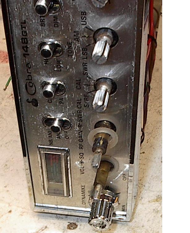
2. Remove all of the knobs on the front of the radio. Take note of the plastic washer/protectors located behind the dual knobs. Make sure you replace these when you reassemble the radio.
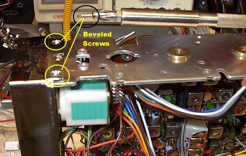
3. Remove the beveled screws holding the faceplate on the radio. Two on each side.
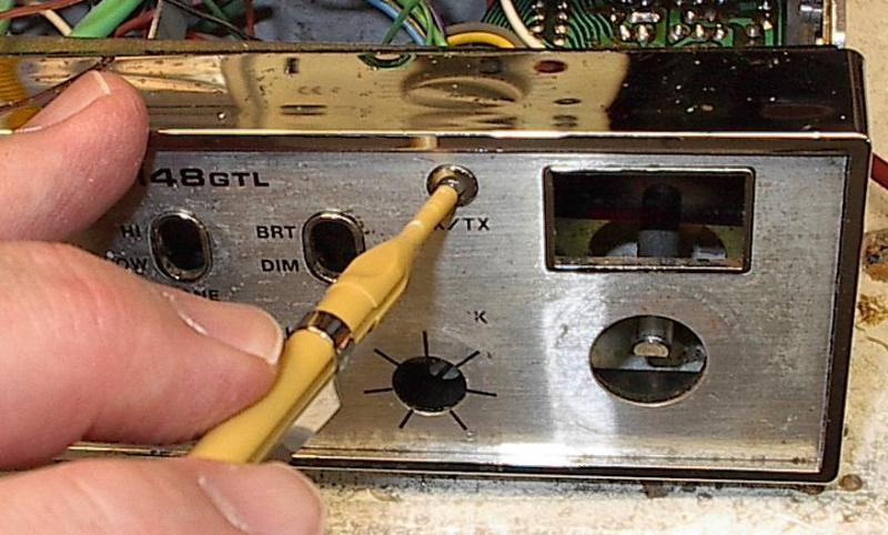
4. Gently pull the faceplate away from the front of the radio. You will need to push the XMT/RCV LED out from the front of the faceplate using a small plastic tool. Remember to glue it back in place when you reassemble.
5. Next we will need to unattach the front metal frame. Remove one screw each side as shown.
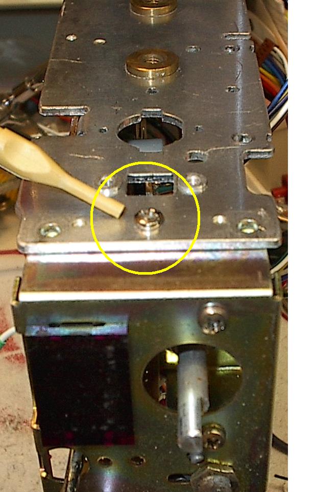
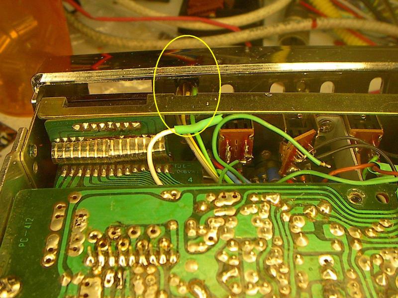
You will then need to remove the PCBd support bracket screw from the bottom front center of the PCBd as shown.
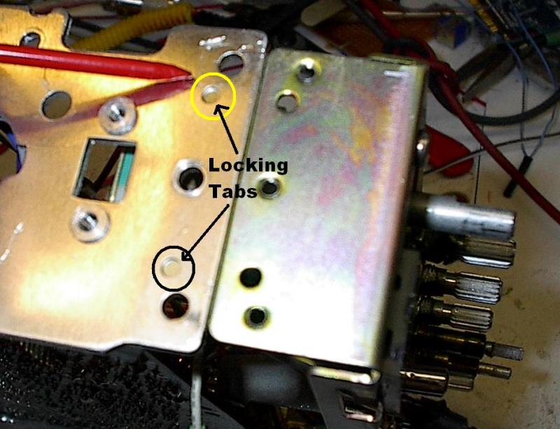
You will also need to gently lift the side frame at the front to release the indented locking tabs on each side.
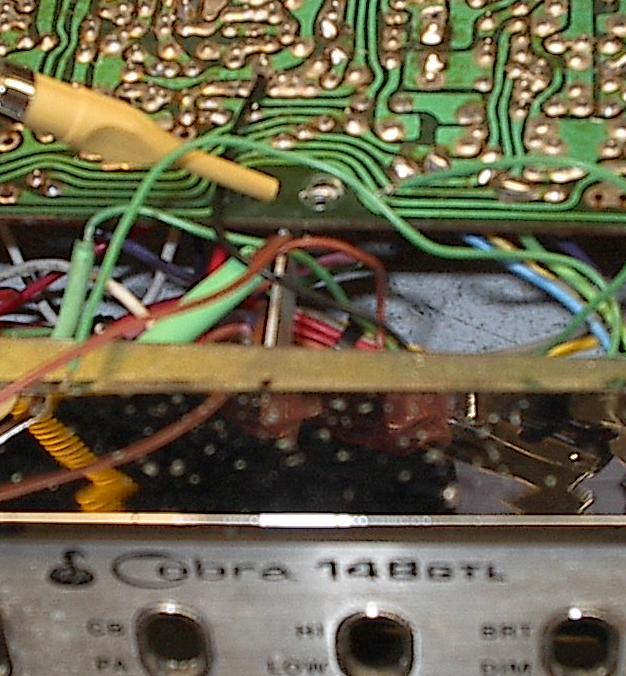
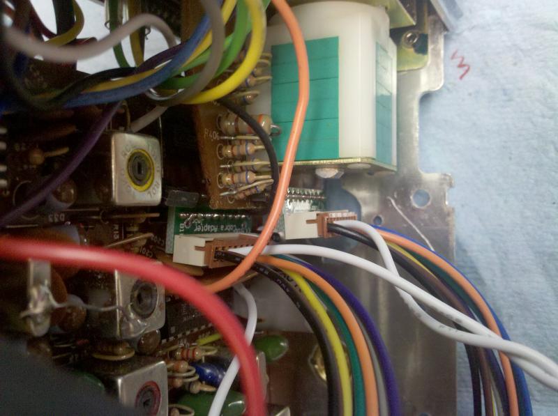
6. Unsolder and remove the multi wire cable, that comes from the channel selector board, to the main board.
.
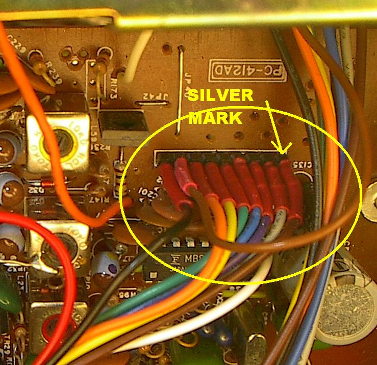
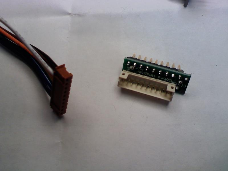
7. Wire connector 1 to the channel selector board as shown. Take note of the Silver or "<<SIDE" mark. This side goes to the outside of the main board.
Plug the loose end into J1a, (labeled 979) on the LesComm board.
THE SILVER or "<<SIDE" MARK GOES TOWARD THE OUTSIDE
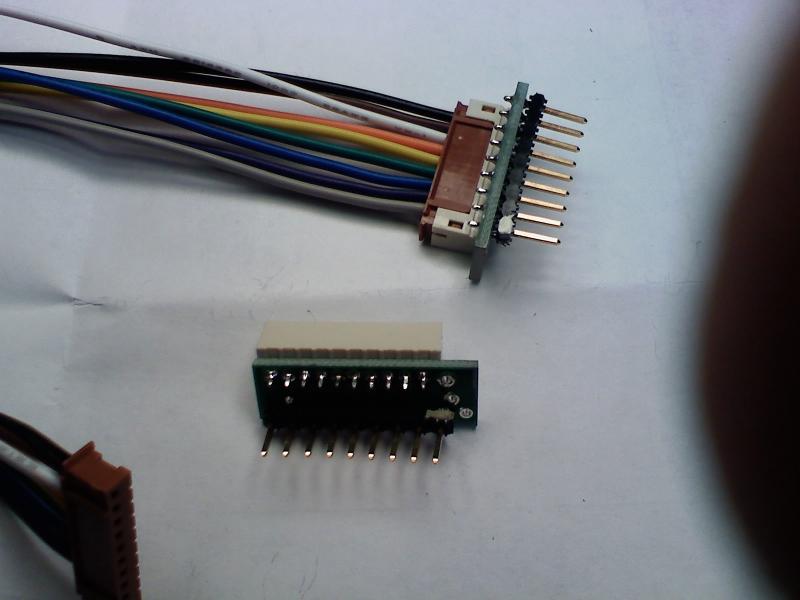
8. Wire connector 2 to the main board as shown. Again, take note of the SILVER or >>> MARK. Connect the cable to J3a (labeled 979) on the LesComm board.
 9. Remove R95. Located close to the PLL IC. If your VCO still will not cover all the bands, replace R98 with a 120k ohm.
 10. Find a suitable place to Mount the LesComm board, install the band switch and the 10kc switch.
11. Connect to power and power up the radio. STOP. Check for full coverage. If full coverage is present, you’re done. Replace covers. If not, proceed to step 12.
12. Place the Band switch in the D (4) position, channel selector on channel 1.
13. Check for the frequency of 27.415mhz/u41-Lo Range or 28.255mhz/125-High Range. If not present, using a digital voltmeter, measure the voltage on pin 17 of the 8719 PLL chip. (Should be approximately 4 volts.)

14. Connect the voltmeter to test point 1 (Cathode of D1) on the LesComm board. Refer to Figure 1.
15. If Fujitsu MB8719, Adjust VR1 to match the voltage you measured on pin 17 of the PLL, minus .1 volts.
Example; If you measured 3.65 volts on pin 17, set VR1 for 3.55 volts at TP 1.
Note: If using an MMB8719, set voltage .2 volts below pin 17.
16. Check for full coverage. If not achieved, adjust VR1 up or down slightly until desired frequencies are obtained.
If after you've adjusted VR1 properly your radio still doesn't cover the whole range, make the following changes. For extended VCO coverage change R98 to 33k ohms and R96 to 100k. If after this your radio still will not cover the entire range, then the VCO module is likely the cause.
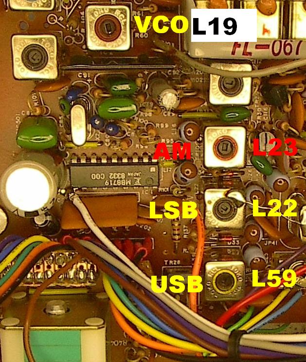
Alignment
Use the alignment locator below for adjustment locations.
Switch to Band C, channel 1, Clarifier at the 12 o'clock position.
Using a Non-Metalic tool,
In the AM mode, adjust L23 for 26.9650 mhz on the counter.
In LSB mode, adjust L22 for 26.9650 mhz.
In USB mode, adjust L59 for 26.9650 mhz.
Reassemble your radio and Enjoy!
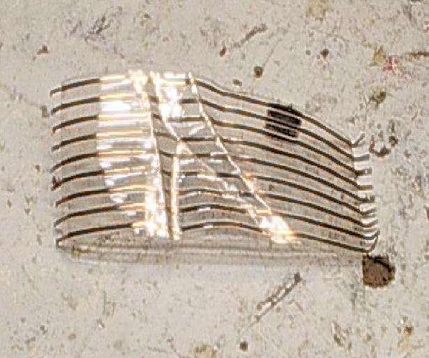
NEW CABLE DESIGN WITH CONNECTION ADAPTERS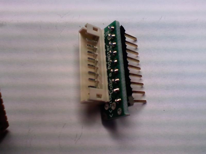
If you're still having problems, double-check the following;
Check that A15 is +5 volts. A15 is located close to IC1 and the regulator circuit, on the J1 side.
Ensure that RA1’s common pin is to +5 volt hole (pull up).
RA1’s common pin is denoted by a dot above the pin.
Side Notes; Power falls off at the ends of coverage on the Uniden made radio’s more than the Ranger made units. It is possible to balance out the power from the top to the bottom, but that’s not covered here.
The RCI8719-97 is a 7 bit device, but the internals of the IC do not allow it the control of the VCO as well as a -99. If your 148F has the -97 RCI PLL, I recommend you replace it with an RCI8719-99 or Micronix MMB8719 and change the crystal. You’ll be much happier with the results.
There are several different versions of the Cobra 148. The instructions presented here are for the most common types. Denoted by a side mounted microphone connector. These instructions also apply to the President or Uniden Grant.
We recommend you obtain a constant readout frequency counter such as the FC347. Instructions on how to wire it to the radio are located here; http://www.cbtricks.com/radios/galaxy/fc347/index.htm
Lester's Custom Truck Shop
United States
Webmaste