Lester's Custom Truck Shop
United States
Webmaste
This module should only be installed by a competent technician. video help; https://www.youtube.com/watch?v=p508ofABSqs
PC122/(146GTL part #'s)
1. Most important! Make sure the radio works in all modes on every channel. Both transmit and receive.
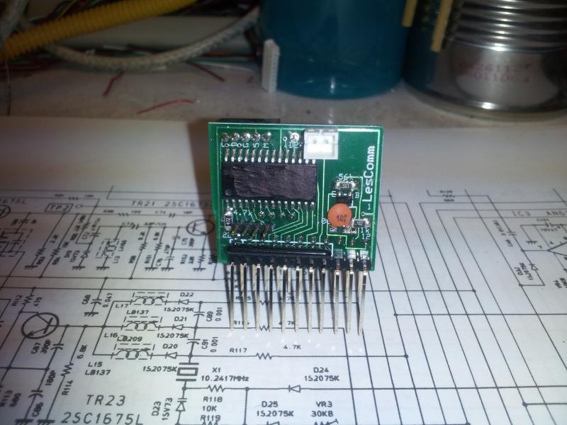
2. Be sure to note the PLL IC2's orientation and then remove IC2. Install the LC2824 in it's place. "V" denotes pin 1.
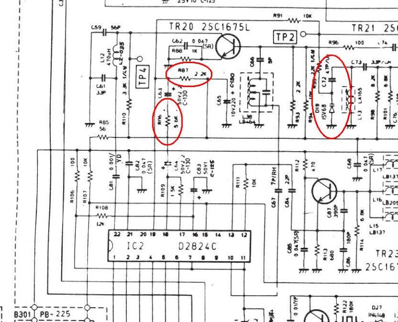
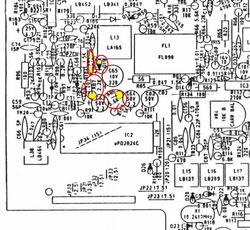
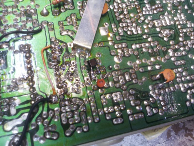
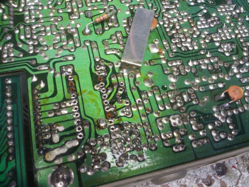
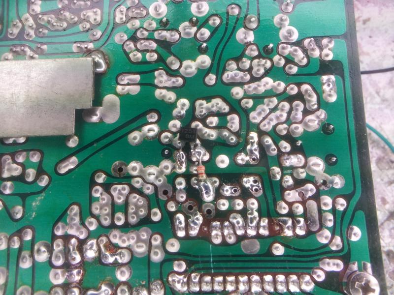
3. Remove R86, R87. Replace R95/(R93) with a 3.3K resistor.
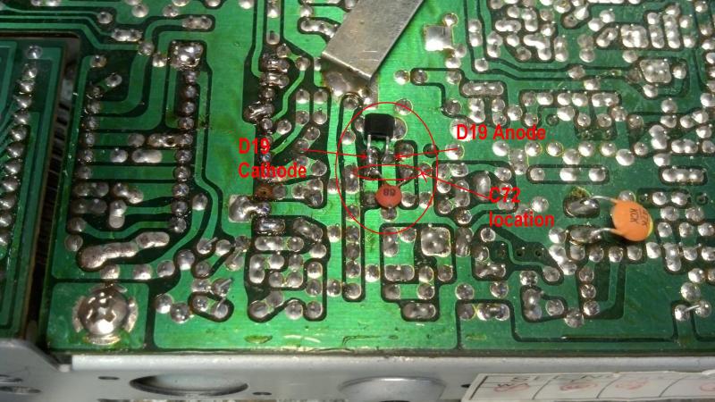
4. Replace D19/(D25) with the enclosed SV251 varactor.
5. Parallel D19/(D25) on the bottom with the second SV251 varactor. You can try to insert both from the top if you like. Looking at the part number side of the varactor, the cathode is on the right, where the "1" is located.
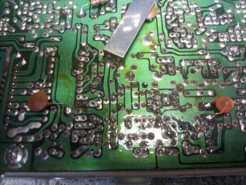
6. Next parallel on the bottom C72/(C75) with the enclosed 68pf cap. Or replace C72/(C75) with a 115 to 120pf cap.
6a. Add a 4.7K resistor between pin 19 and pin 21(Gnd).
7. Connect the +8 wire to the center leg of TR35, +8vdc regulator.
Stop here and power on the radio. Adjust L13/(L14) for full coverage. Note some radio's will not cover the whole range, no matter how much you adjust. Most should at least go down to 26.505 and up to 28.005. If the frequency isn't stable, adjust L38/(L13) for max output at TP4 on 27.205 AM mode.
8. If desired, Connect a wire from the TX/RX LED on the display board to an +8volt receive only source. (Collector of TR31, 2SB525). This turns on the blue LED in receive.
9. Remove the faceplate and then remove the display PC Board.
**Remember that the On/Off/Volume control must be unsoldered from the control PC Board. It is mounted to the faceplate, not the PCB like the rest.
PC122, TRC465
10. Remove all of the resistors located on the Channel-Selector/Display PCB except the 1k ohm resistor located next to the ribbon cable just under "uniden" for the TX LED.
11. Install the new Display PCB in the old ones place. Plug in the display connector from the LC2824smt to the new dispaly board.
PC122 Blue only. Now gently lift the faceplate decal/label over the display LED and remove the RED filter. The clear area on the decal will protect the display and allow the Blue numbers to shine through. A blue sheet cut to the correct size works great as a replacement for the red filter.
For the 146GTL/PC244/AR144 etc.
10. Remove the original 2 digit display. Edge cut the holes using a small drill bit. Be sure all of the holes are isolated from the pc board runs.
11. Insert the new 3 digit in the old display's holes. Be sure the decimal points are at the bottom.
11a. Insert the pins through the Piggyback board and solder in place. Plug the display connector into the Piggyback board.
12 Test your work. If all is well, reassemble. And enjoy your new radio. If you ordered the frequency counter harness kit, go to step 25 for install instructions.
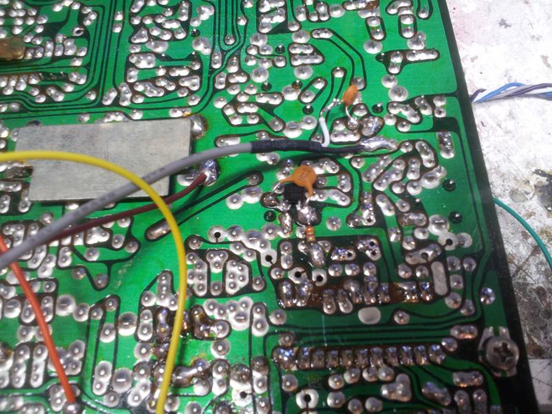
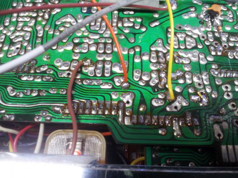
PC122-illustrations
PC122
PC122
PC122
PC122
======================================================================================
146GTL/PC244 illustration
Step 25. Counter harness connections. (146GTL)
Lester's Custom Truck Shop
United States
Webmaste