Lester's Custom Truck Shop
United States
Webmaste
8719-192-L3S Washington, President/Uniden 5 pin Madison & Cobra 142 KIT INSTRUCTIONS

NOTE: RADIO MUST BE IN ORIGINAL CHANNEL CONFIGURATION. ALL CHANNEL MODS MUST BE REMOVED AND COMPONENTS RETURNED TO ORIGINAL CONDITION.
All photo's are Zoom enabled.
Presteps;
Radio must have an MB8719 or equivalent PLL
1. Remove bottom and top covers.
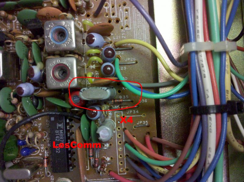
2. Replace X4 (11.1125/11.3258) with the enclosed xtal assembly.
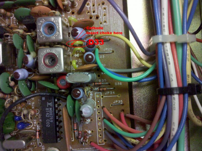
2a. Lift the Cathode end of D33 (1S1588) and insert the enclosed 3.3uh choke between the diode and pcboard.

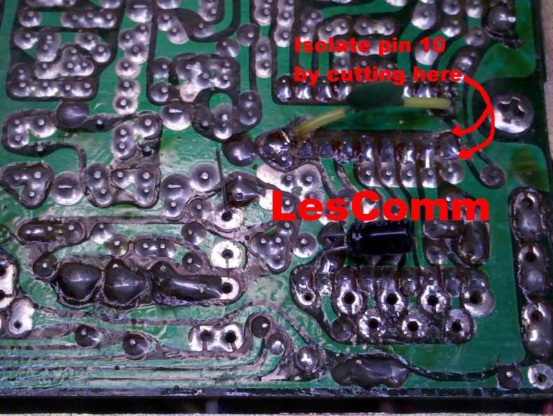
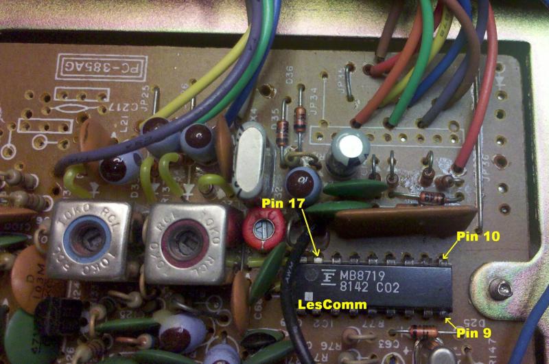
3. Since Pin 10 is permanently grounded, we must isolate it so we can use it. Cut the ground plane run as illustrated below. *** On the Madison with a PC411AD board, pin 10 is already isolated from ground.
4. Connect the WHITE (BROWN for 142) wire from connector J3a to pin 10 of the PLL.
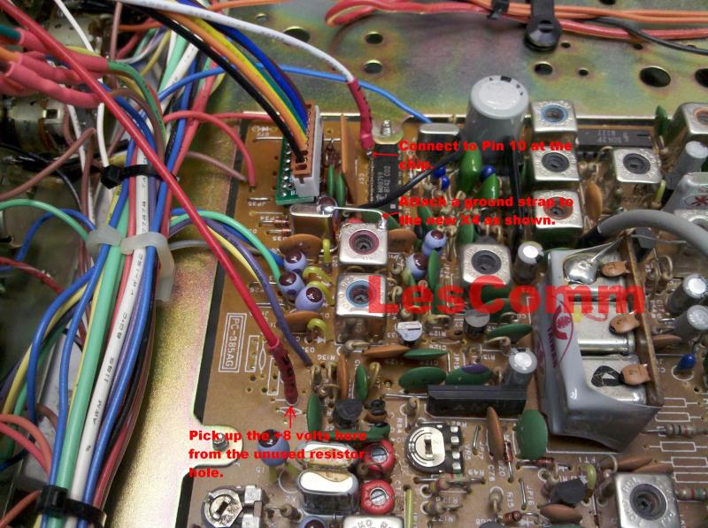
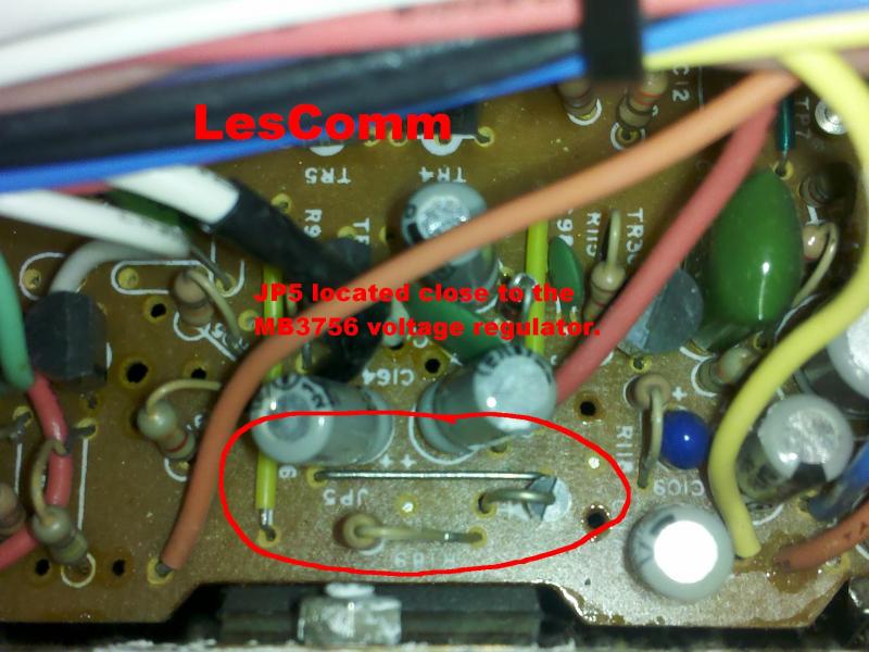
5. Connect the RED wire from connector J3a to J5 (below) or the empty Resistor hole as illustrated above (if available). This is the best place to pick up a clean 8 volts.
CAUTION! Connecting your radio to the wrong set of connectors could permanently damage your radio!!
6. Locate the muti colored wires coming from the Channel Selector board and connecting to the main board. Make sure the colors in the pigtail harness match the colors in your radio! If not, STOP!! Contact Tech Support.
7. Unsolder the six multi color wires shown - only, at the main board, that come from the channel selector board, to the main board.
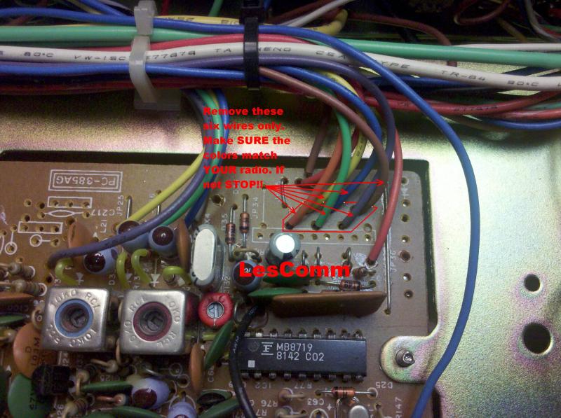
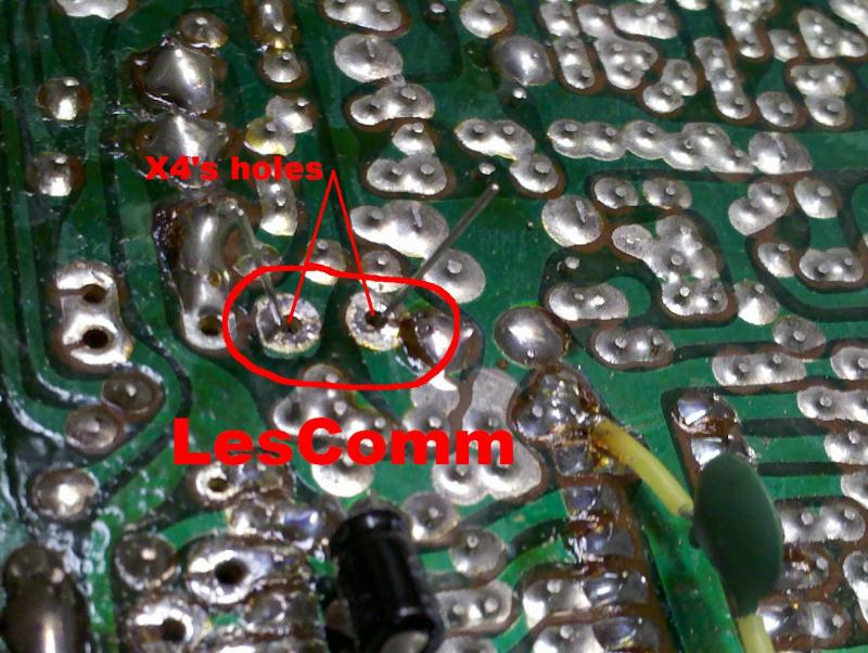
8. Clean out these holes.
.
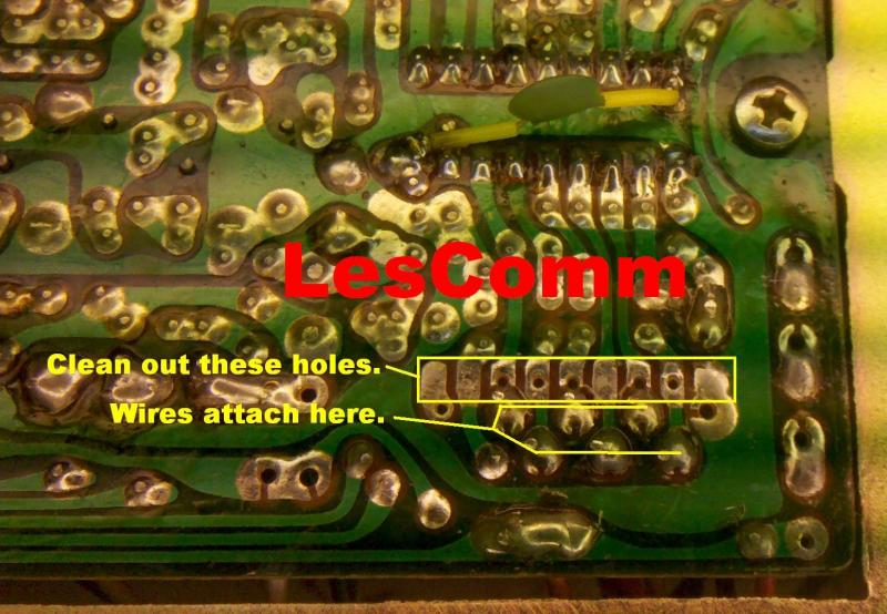
9. Wire connector J1 pigtail to the same color wires coming from the channel selector, like shown.
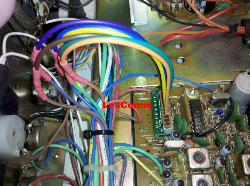
Plug the loose end into J1a, on the L3S LesComm board.
The picture below shows the wires from the channel selector properly connected to the J1a cable and heat shrink protects the solder connection. The cable can be plugged directly into the Cobra Adapter to bypass the Lescomm board and restore the radio to operation for troubleshooting purposes. But you must reground pin 10 for it to work.
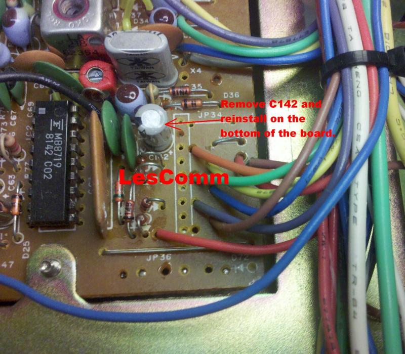
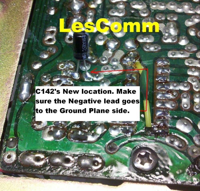
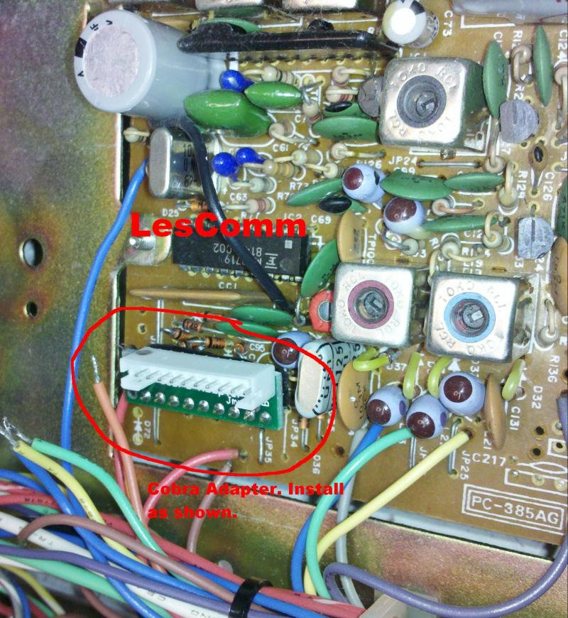
10. C142 gets in the way of the Cobra adapter connector, so we must move it to the bottom. Remove C142 and install it on the bottom of the board as shown. Then install the Cobra adapter to the main board as shown. Again, take note of the "<<<SIDE" MARK. Connect the cable to J3a on the L3S LesComm board.
THE <<<SIDE MARK GOES TOWARD THE OUTSIDE
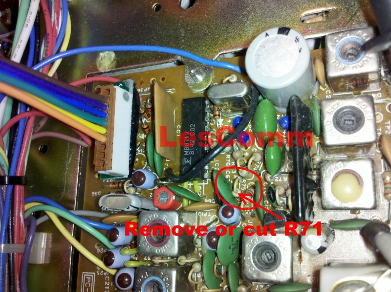
11. For better VCO coverage, cut or remove R71. Located close to the PLL IC.
12. Using the enclosed bracket mount the L3S to the radio.
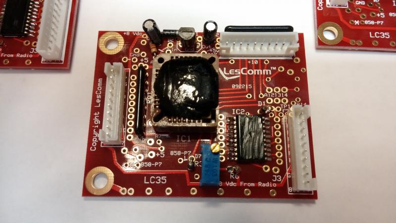
Mount the LesComm board as shown with components facing up.
13. Next replace the Mic Gain or Tone control with the Band switch. Just turn the Mic Gain up all the way or set the Tone to the desired level, and secure it behind the control panel. Make sure it is insulated from shorting out either itself or another electrical connection. Install the band switch.
**If installing the L3S-3B, find a suitable location for the toggle switches and mount. The 3 position switch is the Band switch and the two position switch is the +10kc switch.
14. Find a suitable location for the 10kc switch or use one of the switches already in the radio for a stealth installation.
15. Connect to power and power up the radio. STOP. Check for full coverage. If full coverage is present, proceed to the Alignment section. If not, proceed to step 16.
16. Place the Band switch in the D (4) position, channel selector on channel 1.
17. Using a digital voltmeter, measure the voltage on pin 17 of the 8719 PLL chip. (Should be approximately 4 volts.)
18. Connect a digital voltmeter to test point 1 (Cathode of D1) on the LesComm board.
19. Adjust VR1 to match the voltage you measured on pin 17 of the PLL, minus .5 volts.
Example; If you measured 4.65 volts on pin 17, set VR1 for 4.15 volts at TP 1.
20. Check for full coverage. If full coverage is not present, go back to step 16.
If after you properly adjust VR1 your VCO still will not cover all the bands, replace R74 with a 33k ohm and R73 with a 150k ohm. R73 is the next resistor closer to the PLL from R74.

Reassemble your radio and Enjoy!
Alignment
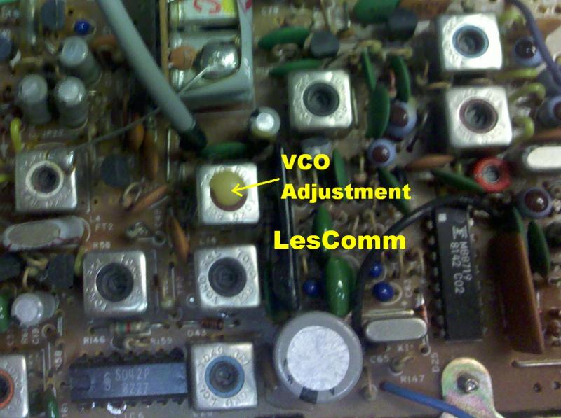
Use the alignment locator below for adjustment locations.
Switch to Band C, channel 1, Clarifier at the 12 o'clock position.
Using a Non-Metalic tool,
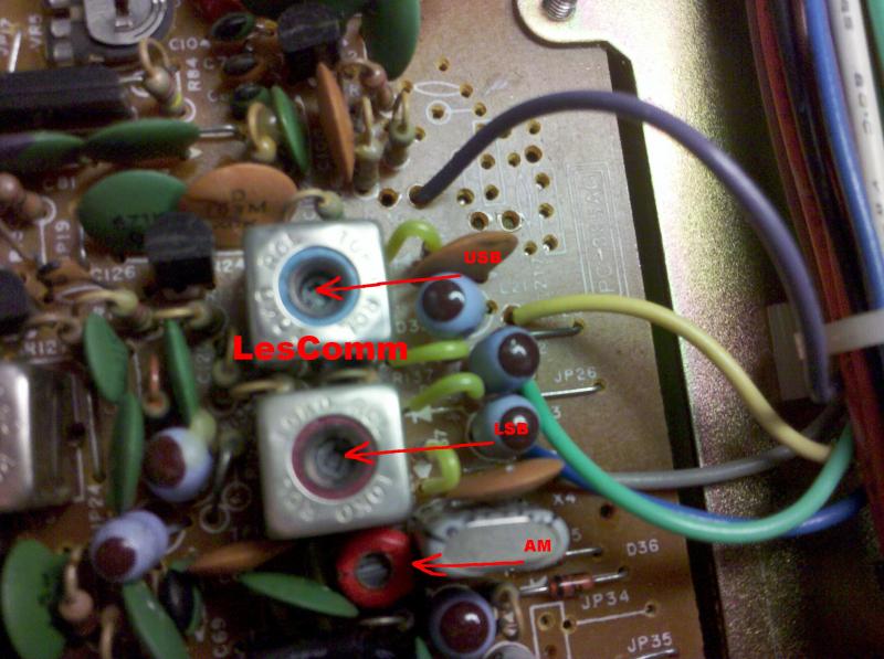
In the AM mode, adjust CT for 26.9650 mhz.
Inject a stable 1000Hz tone via the microphone.
In USB mode, adjust L for 26.9660 mhz.
In LSB mode, adjust L for 26.9640 mhz.
Switch to Band A, channel 40. While measuring the voltage on pin 6 of the PLL, slowly go down in channels until this voltage becomes unstable and drops off. This is the lowest frequency the radio will cover. With the new crystal, usually around 26.175 without VCO adjustment. If needed, you can make VERY SLIGHT VCO adjustments to get coverage at both ends of the bands. But remember, until you do the broadband mod, output power and receive sensitivity will fall off at the ends.
Reassemble your radio and Enjoy!
Side Notes; Power falls off at the ends of coverage on the Uniden made radio’s more than the Ranger made units. It is possible to balance out the power from the top to the bottom, but that’s not covered here.
These instructions also apply to the 5 pin President or Uniden Madison.
Madison colors;
Red
Orange
Yellow
White
Blue
Pink or Lt Green
Lester's Custom Truck Shop
United States
Webmaste