Lester's Custom Truck Shop
United States
Webmaste
Return to store; "httpS://store.lesterscustoms.com"
LC5304 & LC6404, LC5200 & LC6200 INSTRUCTIONS
YouTube link; LC5304 Install in a Philippine Cobra 148GTL


NOTE: RADIO MUST BE IN ORIGINAL CHANNEL CONFIGURATION. ALL CHANNEL MODS MUST BE REMOVED AND COMPONENTS RETURNED TO ORIGINAL CONDITION.
CHANNEL SELECTOR OBSERVATIONS
As you are now aware, we're using the channel selector instead of an encoder with our new LesComm boards. This makes installation a lot simpler. However, channel selector switches are sloppy when it comes to switching contacts. Most channel selector switches "break before make". What this means is that there is no smooth transition from one position to the next. It's a phenomenon mistakenly referred to as "contact bounce". However in this case the contacts are actually making and breaking contact. Not bouncing like relay contacts. Instead of the switch going straight from a count of say 5 to 6, it's more like 5 to 7 to 25 to 18 to 12 to 6" as the contacts make and break. (Remember, 8 bits and 40 positions). Radio manufacturers compensate for this by muting the radio audio between channels. So what we've done is write code that has the processor wait until the contacts have settled. It looks at the input over a specific time period to see if the value is still changing. If it is constant for more than a given period it then measures the input. This all happens in a minute period of time less than one tenth of a second. While this works 99% of the time, there is still that 1% where it doesn't. What this means to you is that it may take 2 clicks sometimes to go up or down 1 channel. We think you’ll agree it’s a small inconvenience considering the benefits.
We are pleased to report that this anomally has been virtually eliminated!
Presteps;
If you requested the Low-Range of frequencies;
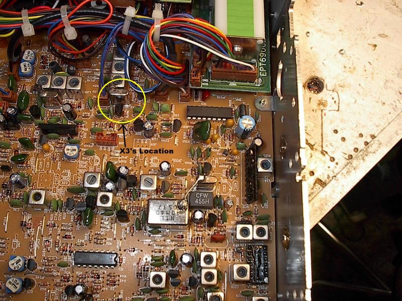
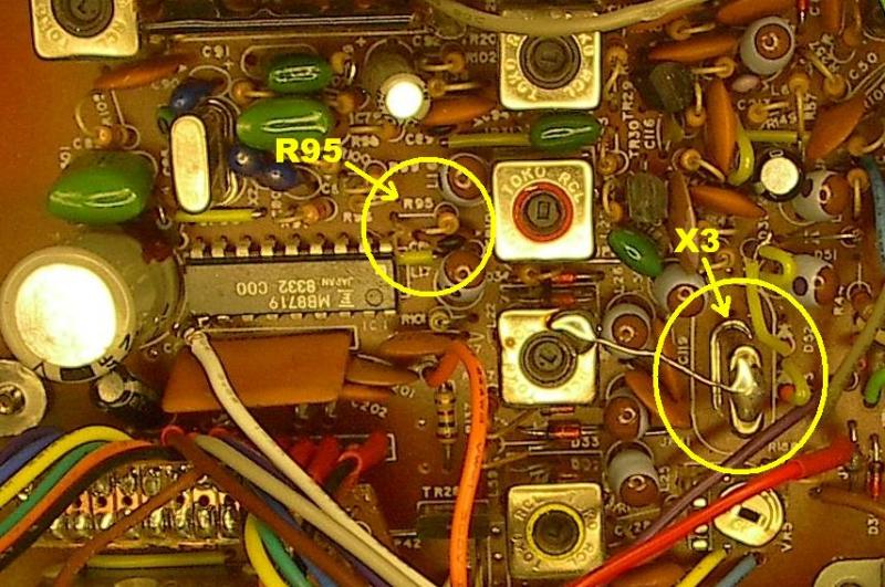
DX959, 949, 939, 2547, Ranger 69X, 96X, Freedom-1, replace X3 with the 14.73 xtal.***
Cobra, replace X3 with the 11.07 xtal and cut or remove R95.
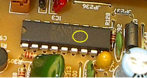
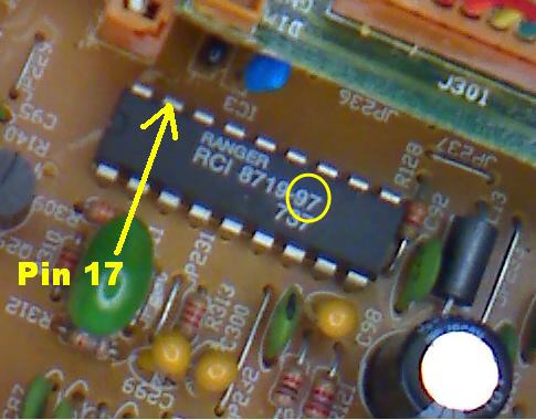
***Ranger / Galaxy EPT069610Z & 11Z, Refer to figure 1. If your PLL IC is labeled like the one in this pic “RCI 8719-97” replace with a “RCI 8719-99” or MMB8719.

Figure 1.
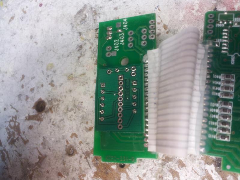
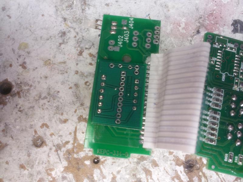
Take note of the connector labels. 1 goes to the channel selector connector/adapter, J3 goes to the radio connector/adapter.
CAUTION! Connecting your radio to the wrong set of connectors could permanently damage your radio!!
1. Remove the top and bottom covers.
2. Ranger/Galaxy; REMOVE the multi colored cable, that comes from the channel selector board that goes to the radio connector.


On the Cobra/Uniden radio's, install the connector/adapters as shown below. For the Cobra 2000 and Madison, connect the same color wire's to the adapter pigtail as shown. Refer to the Cobra 2000 instructions for more details.
VERY IMPORTANT**
If your board is equipped with a "DLL" input connection.
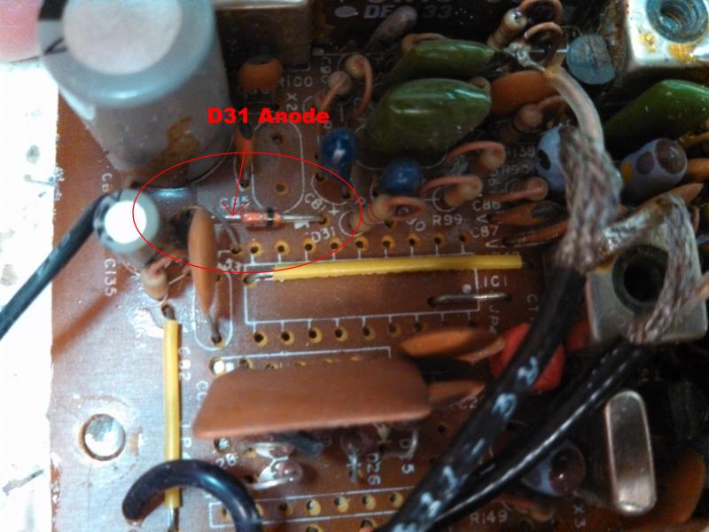
Connect the single wire coming from the "DLL" input pin to the ANODE of D31 on the 148, 2000, Grant and Madison. D25 on the 140, 142 and Washington . And the Cathode of D40 on the PLL858 Uniden boards.
On the Cobra 2000GTL, if using the 3-Digit display, remove the gray wire at the main board!! This wire contains 8 volts that can damage the cpu on the LesComm board with the right channel selection pins combined.
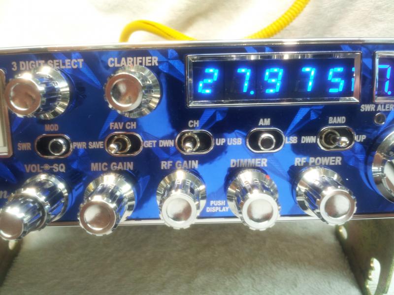
New Cobra 148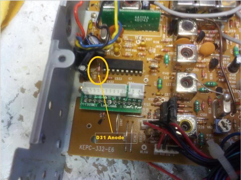
Uniden Madison 5 pin D31
Galaxy 959, connect the DLL wire to the pin 6 side of R128.

On the Uniden PLL858 chassis, connect to the Cathode of D40.![]()
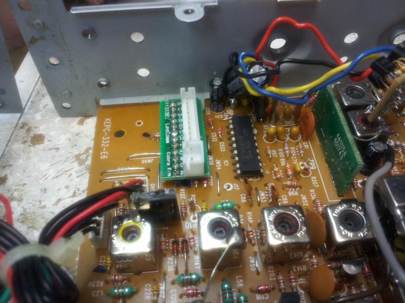
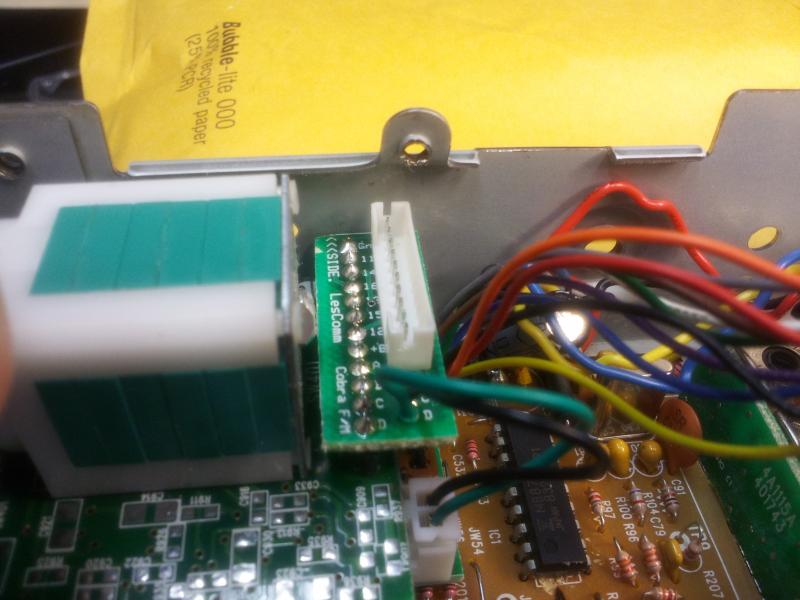
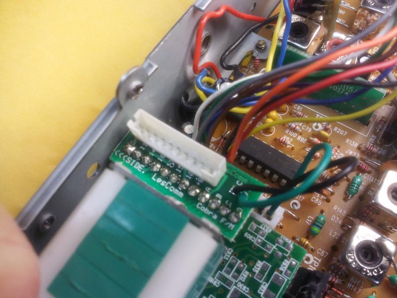
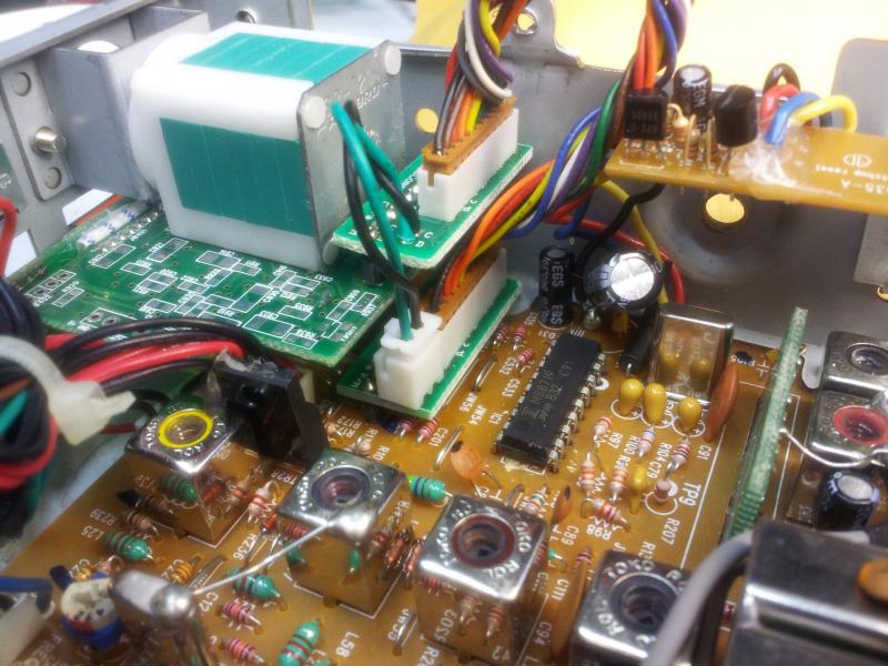
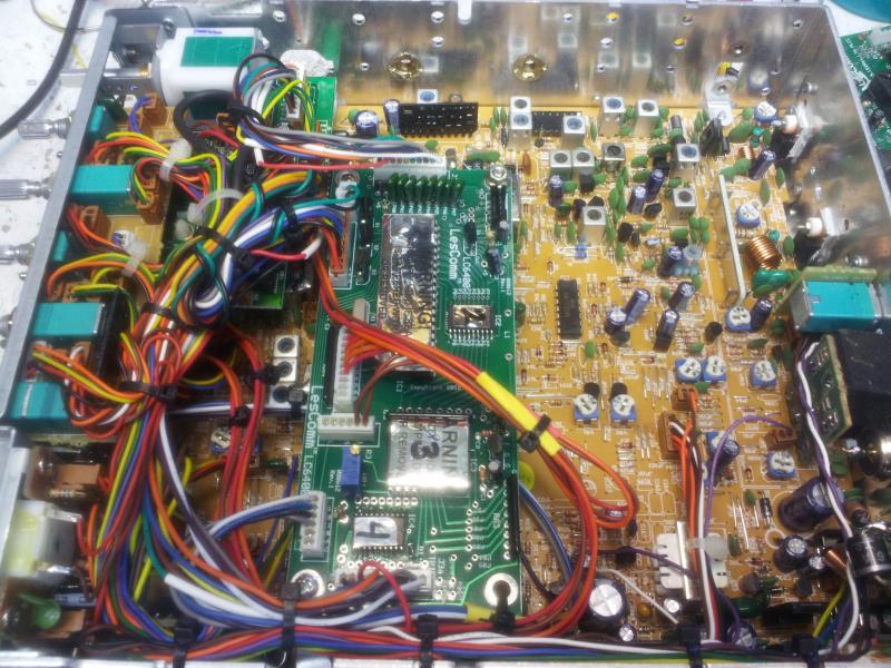
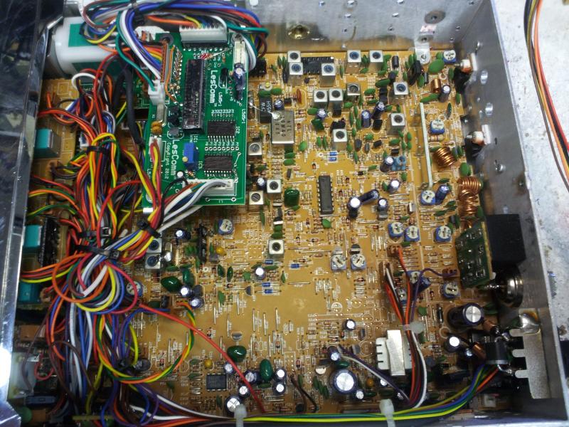
3. Using the cables supplied with the LC5300/6400, plug the cable from J1 of the LesComm board into the channel selector board.
4. Connect the cable from J3 of the LesComm board to the connector on the main board of the radio.
5. Find a suitable place to install the band up/dn switch and the channel up/dn switch (LC6400 only) and mount both.
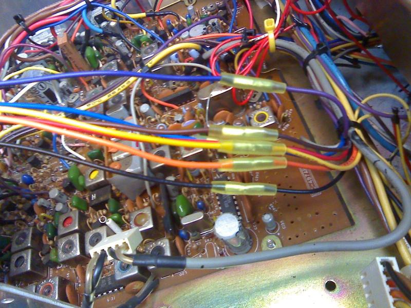
6. Connect the RED power wire to the center leg of Q37 on the Galaxy or Ranger. Q37 is mounted on the side of the chassis. Leave the leg in place, just connect to it.
On the Cobra's, either connect the RED power wire to pin 1 of the MB3756 if so equipped or to the Cathode of D4 if your radio uses the 7909 voltage regulator. D4 is located directly in front of the voltage regulator.
DO NOT CONNECT TO J29!
IF YOU ORDERED THE INTERNAL DISPLAY go to step 7. If not, go to step 8.
7. Mounting the internal display.
On the Cobra 2000, simply remove the channel selector by removing the knob, then using a 11mm deep socket to remove the nut holding the channel selctor in place. Remove the two screws holding the two digit display board in place and install the 3 digit where the two used to be. At this point you can either tape up the two digit display and leave it inside the radio or simply cut the wires connecting it to the channel selector board. I like to remove all of the resistors and unsolder the wires connecting the display. But that's not necessary. If you leave the display connected, you can restore the radio stock easily.
Other Base radio's and Mobiles; Do not un-bridge any of the connections.
It is better to isolate only the 11 holes that the new display's leads will go through.
Leave all other connections in place.
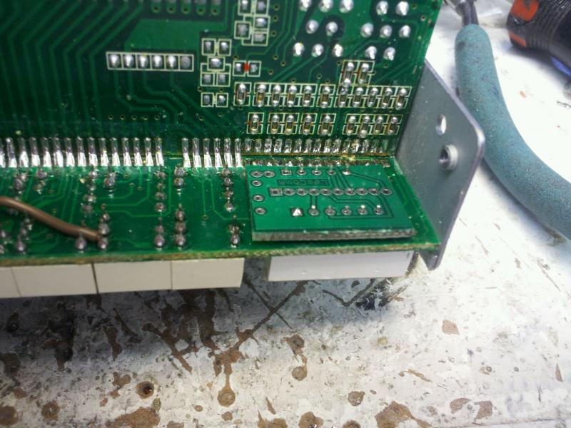
Using a drill bit by hand, edge-cut all 11 holes that the new display will go through.The 6 center holes at the top and 5 holes on the bottom. Edge-cut on BOTH sides of the board!! Use a big enough drill bit so that the sipp connectors or display pins cannot touch the old pc runs on the front.
You're isolating the plated through holes so that the new display can not electrically touch the runs the old display were connected to.
Make sure there is no way for the new display to touch any of the pc runs on either side of the board. I can't stress this enough. Double - double check and make sure they are isolated.
Pay particular attention to the bottom two holes because they are connected to each other. You must separate them as well.
It's difficult to remove the display and piggy-back pcboard after the connectors are soldered in place.
Once you have the 11 holes isolated, if not bent already, bend the leads of the new display to match the wider holes of the old display. Use the piggy-back board as a template.
NOTE: If the display ever fails (not likely) it is better to cut the pins from it to separate it from the piggy-back board and then desolder the pins with the piggy-back board out of the radio.


Next, insert the new 3-digit display into the sipp stand-offs. Check to see if there is enough room for the sipp connectors and the display behind the faceplate window. There is not enough room on some radios. If there isn't enough room, just insert the display pins through the holes. Decimal points to the bottom, and mount the piggy-back to these. Get them as tight together as possible.
The sipp connector does two things. Allows you to easily remove and replace the display and moves it closer to the window so it's easier to see at an angle.
Once the display or sipp pins are soldered to the piggy-back board, insert the 2 pin connector first. Leave it standing high enough that you can get your soldering iron tip in to solder the leads to the piggy-back pcboard. Be careful not to bridge any of the pins with each other. It's easy to do because they're only 2mm apart.
Open side towards the top of the radio. Do the same for the 10 pin connector. Again, open side towards the top of the radio. See the picture below.
Assuming you have the L5300 or 6400 installed, plug the display connectors from the LesComm board to the connectors on the piggy-back board. Make sure nothing is shorted or can short, then power it up.
You should see the LSCM logo come across the display then it should go to channel 19.
If not, you will need to double check your work and try again.


8. If all is well, power up the radio.
STOP. Check for full coverage. If full coverage is present, Go to Alignment section.
If not, proceed to step 8a.
8a. Rotate the channel selector to;
Lo Range Radios: 27.415, u41 or d41.
Hi Range Radios: 28.205, 120.
9. Check for the frequency of 27.415mhz Lo Range or 28.205 Hi Range. If not present, using a digital voltmeter, measure the voltage on pin 17 of the 8719 PLL chip. (Should be approximately 4 volts.)
10. Connect the voltmeter to test point 1 (Cathode of D1) on the LesComm board.
11. Adjust VR1 to match the voltage you measured on pin 17 of the PLL, minus .3volts.
Example; If you measured 4.65 volts on pin 17, set VR1 for 4.35 volts at TP 1.
Note: If using an MMB8719, set voltage .75 volts below pin 17.
We've noticed that some of the Cobra's actually like the voltage at pin 17 a little higher than pin 17. So adjust VR1 to obtain a slightly higher voltage than pin 17 if you do not acheive a lock at 27.415 until you do.
12. Check for 27.41X/28.20X. If not 27.41x/28.20x, repeat steps 9 through 11.
Alignment
Use the alignment drawing below for adjustment locations.
Rotate the channel selector to 26.965/Band C ch-01/c01, Clarifier at
the 12 o'clock position.
Using a Non-Metalic tool,
In the AM mode, adjust L20 for 26.9650 mhz.
In USB mode, adjust L21 for 26.9650 mhz.
In LSB mode, adjust L22 for 26.9650 mhz.
Switch to Band B ch-40/26.955/-01. While measuring the voltage on pin 8 of the PLL, slowly go down in channels until this voltage becomes unstable and drops off. This is the lowest frequency the radio will cover. Usually around 26.325 on the 8719-97 PLL radio’s. 26.065 on the 8719-99 radio’s.
GALAXY/RANGER 69610Z
Cobra Alignment
Use the alignment locator below for adjustment locations.
Rotate the channel selector to 26.965/Band C ch-01/c01, Clarifier at the 12 o'clock position.
Using a Non-Metalic tool,
In the AM mode, adjust L23 for 26.9650 mhz on the counter.
In LSB mode, adjust L22 for 26.9650 mhz.
In USB mode, adjust L59 for 26.9650 mhz.
Cobra 

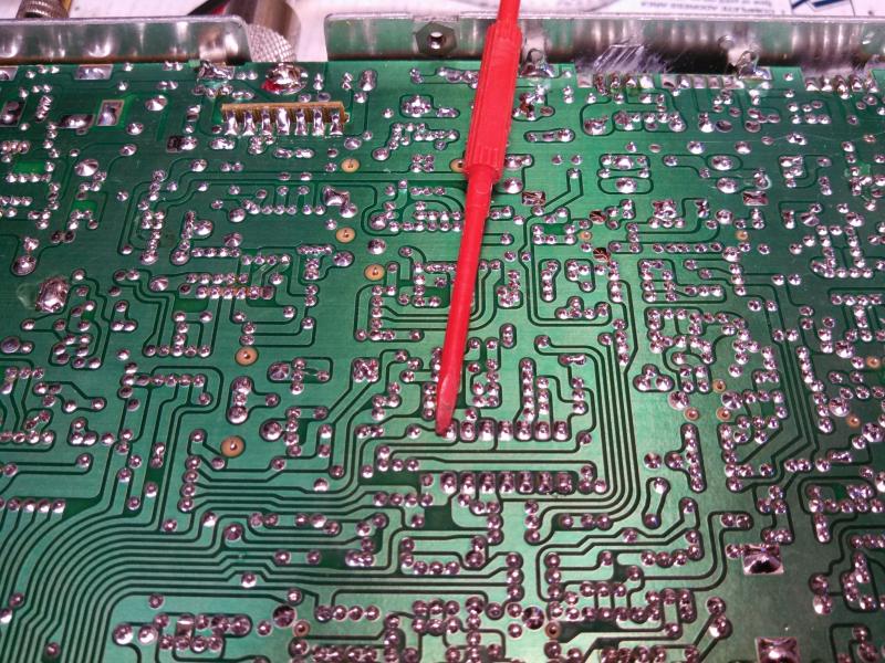
SQUELCH PICK UP POINTS FOR SquelchScanTM
Galaxy DX959/949/2547
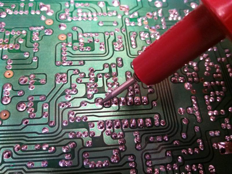
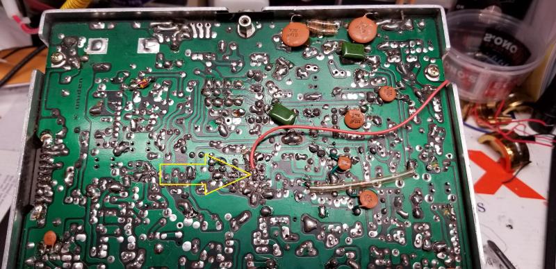
Cobra 148/2000, Grant Silver Face
Philipine 148

Grant XL

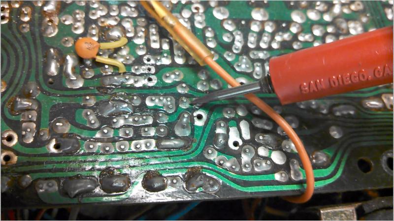
Below is the Squelch pick up point for the PLL858 Uniden chassis.

Side Note; The RCI8719-97 is a 7 bit device, but the internals of the IC do not allow it to control the VCO as well as a -99. I recommend you replace it with an RCI8719-99 or MMB8719. You’ll be much happier with the results.
Lester's Custom Truck Shop
United States
Webmaste